Document Ref · FF-01-2026Build Journal

Touchless
Water
Dispenser

Build journal for a smart, fully-automated dispenser engineered on the Raspberry Pi 5. Written in C++ with interrupt-driven I/O, a finite state machine, and a sub-150 ms emergency stop.

Read Full Journal →v1.0 · STABLE
Total Commits
140+
I/O Drivers
05UNITS
BOM Cost
£31.74
Latency
<150ms
RT constraint verified
Scale 1:1Sheet 01 / 04 · Checked by A.A. + B.M.
§ 01 / STORY

How It All Started

It started with a question we kept asking in the lab: "Why are restaurant drink dispensers so clunky?" You press a lever, you touch a button, you hold a cup at an awkward angle — and half the time you overfill and spill. We thought: what if the machine just knew what you wanted and poured it for you, hands-free?

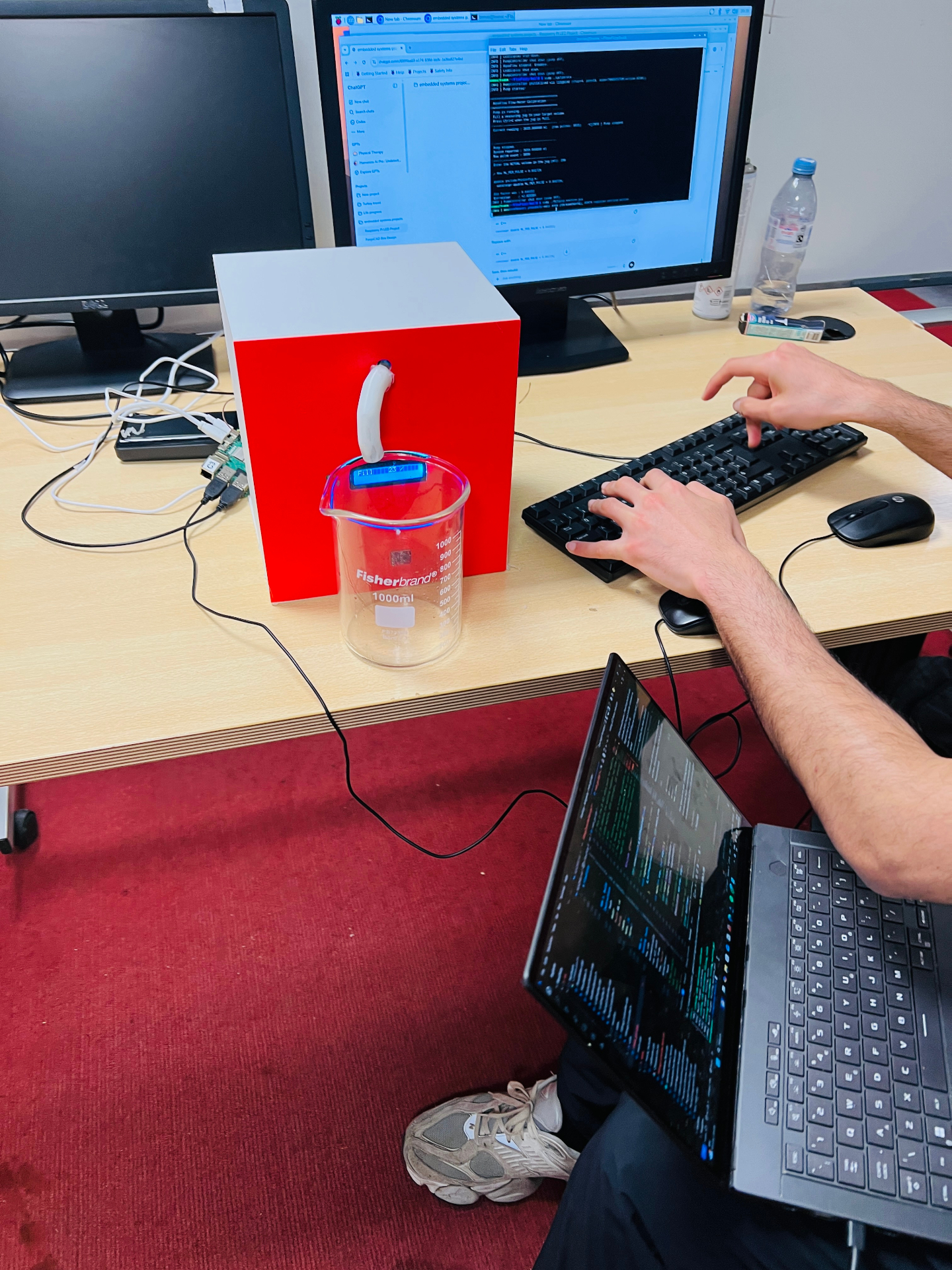
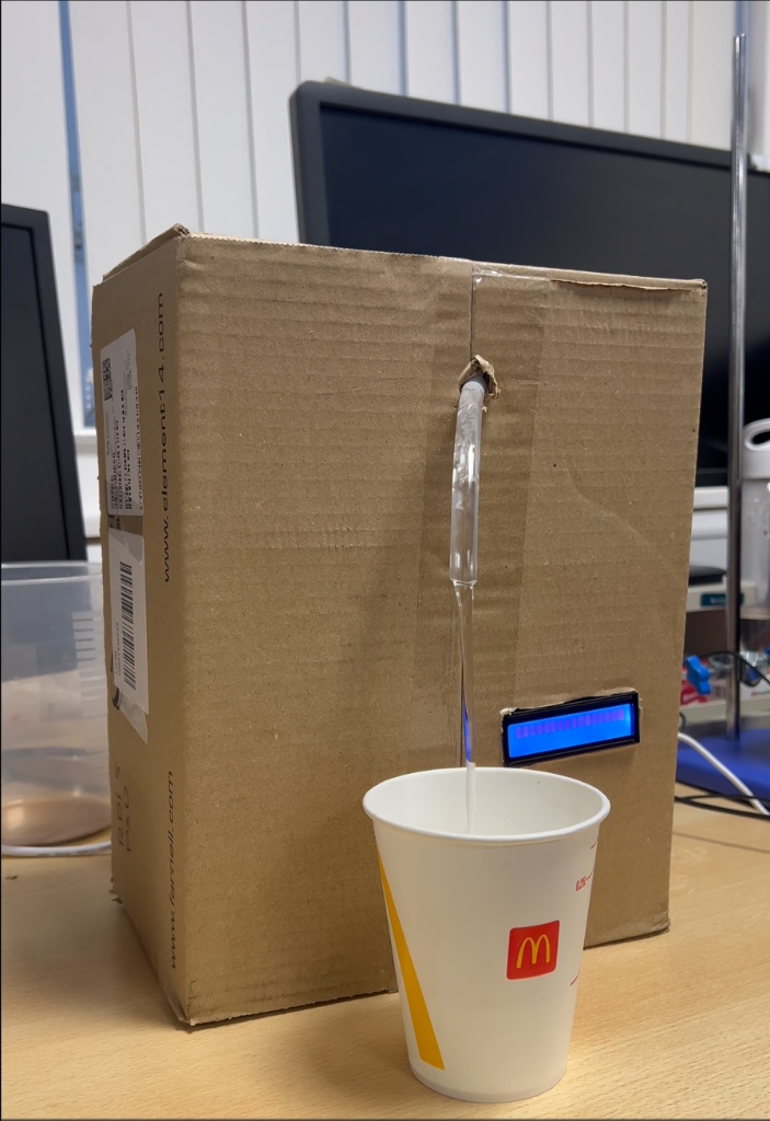
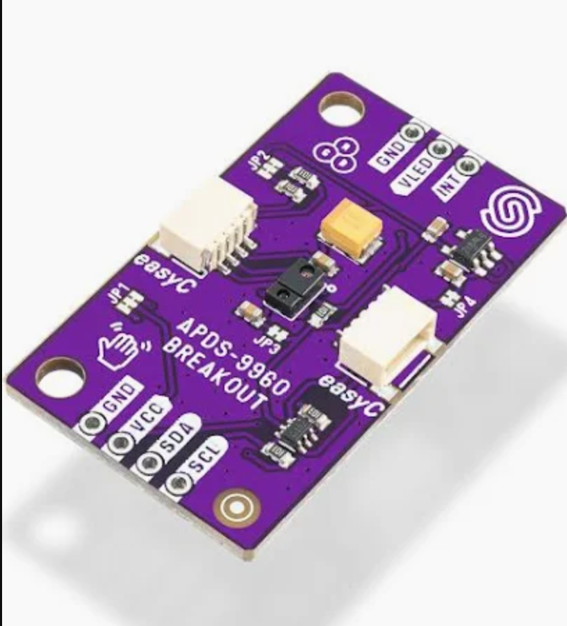
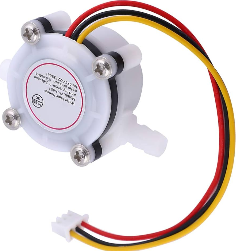
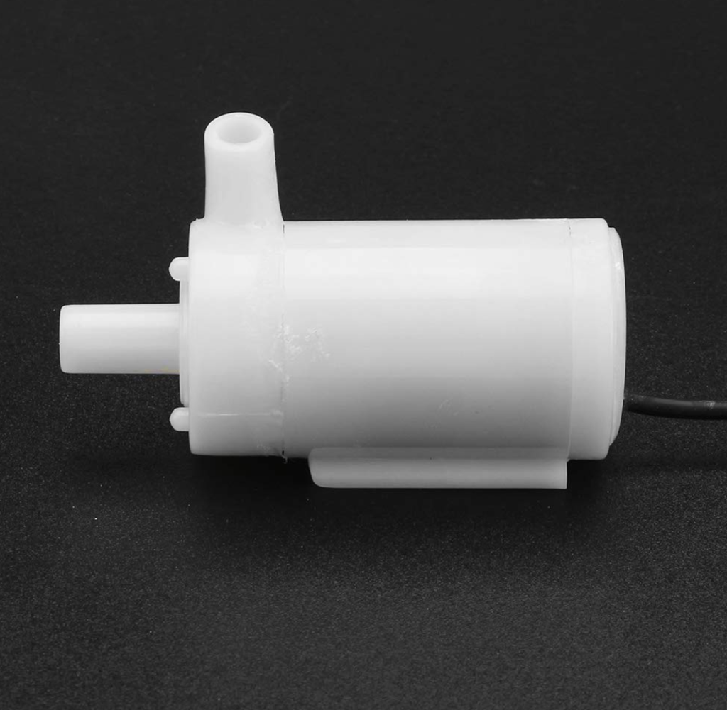
That idea became Aquaflow. Pick a cup size with a button, place your cup on the platform, an IR proximity sensor sees it, the pump fires, the flow sensor counts every millilitre, and the pour stops the instant it hits target. No touching. No spillage. Just precision.

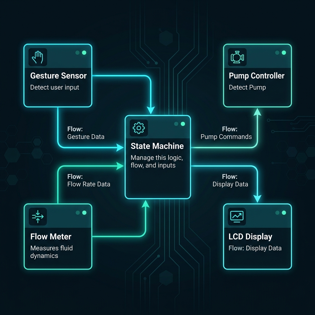
What made it exciting wasn't water coming out of a tube — it was doing it properly: interrupt-driven I/O, a real state machine, SOLID architecture, code that survives a professional review.

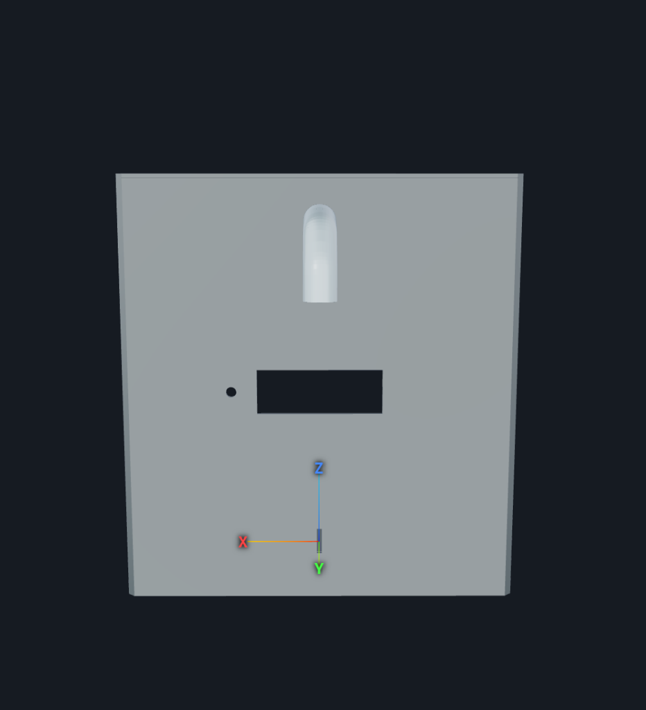
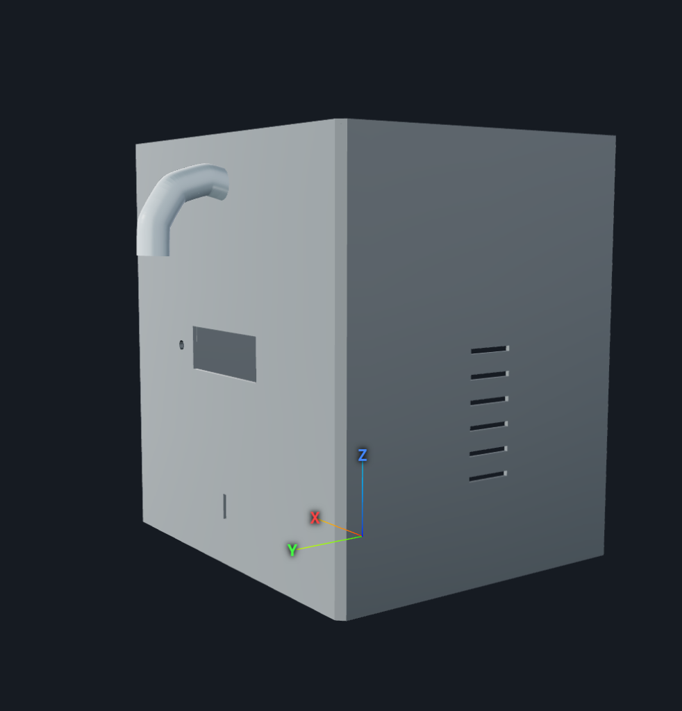
Built over the spring semester in Rankine Lab 509 at the University of Glasgow — from bare wires on a breadboard to a 3D-printed enclosure with an integrated sensor mount.

Aquaflow prototype dispensing into a 1L Fisherbrand beaker in Rankine Lab 509
FIG. 01.A  —  Final build, dispensing into a 1L Fisherbrand beaker. LCD shows live fill progress.
Early Aquaflow demo dispensing into a McDonald's cup from a cardboard enclosure
FIG. 01.B  —  Early days: same touchless pour, cardboard box, McDonald's cup as the test vessel.
§ 02 / HARDWARE

The Components That Make It Work

We deliberately kept the hardware minimal — four active components plus the Pi. The assessment rewards code quality, not component count, so a tight stack let us pour the energy into making the software architecture genuinely excellent.

The Proximity Sensor — APDS-9960
FIG. 02.A  —  APDS-9960 IR proximity board — the heart of touchless cup detection.

The Proximity Sensor — APDS-9960

This tiny purple board fires an infrared beam and measures how much light bounces back. Slide a cup onto the platform and the proximity reading jumps from ~15 (ambient) to 100+ at a 10 cm gap.

Getting it working in C++ was honestly one of the hardest parts. The APDS-9960 has a gesture engine that intercepts proximity data — we spent an entire lab session debugging why PDATA wouldn't update, only to find the gesture engine was stealing the readings.

The Flow Meter — YF-S401
FIG. 02.B  —  YF-S401 Hall-effect turbine sensor — outputs digital pulses as water passes through.

The Flow Meter — YF-S401

Inside the YF-S401 sits a small turbine with a Hall-effect sensor. Each rotation generates a pulse corresponding to a tiny fraction of a millilitre. Our C++ driver counts those pulses through libgpiod edge interrupts with sub-millisecond latency.

Calibration was critical: 4,027 pulses = 260 ml, giving us ML_PER_PULSE = 0.064564 and ±5 ml accuracy on a 500 ml fill.

The Pump — JT80SL Submersible
FIG. 02.C  —  JT80SL submersible pump — switched safely through a TIP122 transistor circuit.

The Pump — JT80SL Submersible

A small 5V DC submersible pump that sits at the bottom of the reservoir. It draws ~220 mA — well over GPIO limits — so we drive it through a TIP122 Darlington transistor with a flyback diode for back-EMF protection.

The LCD — 16×2 I2C Display
FIG. 02.D  —  Classic HD44780 16×2 LCD over I2C — selected size, fill progress, and live status.

The LCD — 16×2 I2C Display

A classic HD44780 over I2C gives real-time feedback: the selected cup size, fill progress (320ml / 500ml), and status messages.

Bill of Materials

ComponentCost
DollaTek APDS-9960 Gesture/Proximity Sensor£4.99
YF-S401 Water Flow Sensor£7.45
JT80SL DC Submersible Pump£5.20
TIP122 Transistor + Diode + Resistor Kit£2.50
16×2 I2C LCD Display£6.10
Breadboard & Jumper Wires£3.50
Silicone Tubing (1 m)£2.00
TOTAL£31.74
Raspberry Pi 5 GPIO pinout
FIG. 02.E  —  Pi GPIO map. Used: GPIO 2/3 (I2C), GPIO 17 (flow), GPIO 18 (pump), GPIO 26 (button).
§ 03 / SOFTWARE

The Architecture Behind the Pour

The software is a strict event-driven, non-blocking architecture. No polling loops, no sleep() calls, no busy-waiting. Every component runs on its own thread, communicating through atomic variables and callbacks.

The State Machine

FillingController is the brain — a finite state machine: SELECTING_SIZE → WAITING_FOR_CUP → CONFIRMING → FILLING → FILL_COMPLETE. Every 100 ms a timerfd tick fires; the controller reads atomic sensor state and decides what to do next.

SOLID — Not Just Buzzwords

The controller depends on abstract interfacesIProximitySensor, IPump, IFlowMeter. It has no idea it's talking to a Raspberry Pi GPIO pin, which is exactly the point.

Interrupt-Driven I/O

The flow meter uses libgpiod edge events — the thread literally sleeps until a voltage change on GPIO 17. No CPU wasted. Same pattern for the physical button on GPIO 26.

Aquaflow system architecture: gesture sensor, flow meter, state machine, pump controller, LCD
FIG. 03.A  —  High-level architecture. Each sensor owns a thread; the state machine ticks every 100 ms.
// listing 03.B — button → controller wiring
// How the button callback is wired — signal-slot pattern
// in AquaFlowApp::start()

button_.registerShortPress([this]{
  controller_.onShortPress();  // cycles S → M → L → S
});

button_.registerLongPress([this]{
  controller_.onLongPress();   // confirms selected size
});
Safety Critical

Emergency stop. If the proximity sensor detects the cup has been removed mid-fill, the state machine kills the pump within < 150 ms — one tick cycle. The flow meter keeps its count, so if the cup returns, filling resumes from where it left off.

§ 04 / TIMELINE

The Build Journey

From first commit to final demo — how Aquaflow evolved over the semester.

  1. ENTRY 01Early March 2026

    First Wires on a Breadboard

    Initial hardware tests — ultrasonic sensor, pump relay. Translated the Python prototype into C++. Early commits were messy README updates and 'test commit' messages.

  2. ENTRY 0220 March 2026

    The Pump Decision

    Switched from the 12V solenoid valve to the JT80SL submersible pump. Wired the TIP122 transistor circuit. Tried powering the pump directly from GPIO (bad idea). Settled on the transistor + flyback diode approach.

  3. ENTRY 03Late March 2026

    Flow Meter & LCD Integration

    Got the YF-S401 counting pulses via libgpiod edge detection. Brought up the 16×2 LCD over I2C. First successful end-to-end fill: pump runs → flow counts → pump stops at target.

  4. ENTRY 04Early April 2026

    Gesture Sensor Saga

    Spent several sessions wrestling with the APDS-9960. Eventually found the gesture engine was stealing proximity data. Stripped it out — proximity-only mode worked perfectly.

  5. ENTRY 0514 April 2026

    The SOLID Refactor

    Major architecture overhaul. Applied SRP to every class. Introduced IProximitySensor, IPump, IFlowMeter interfaces. Routed all output through Logger. The day the codebase went from 'student project' to 'professional.'

  6. ENTRY 0620 April 2026

    Calibration & Interaction Redesign

    Abandoned gesture-based size selection (unreliable). Switched to button-driven model. Calibrated the flow meter: 4,027 pulses = 260 ml. Fixed proximity threshold to 90 for reliable 10 cm detection.

  7. ENTRY 07Late April 2026

    3D Enclosure & Polish

    Designed and printed the enclosure shell with integrated sensor mount, nozzle collar, and ventilation slots using OpenSCAD. The black 3D-printed stand became the signature visual of the project.

  8. ENTRY 08May 2026

    Qt GUI — Real-Time Monitoring

    Built a full Qt5 desktop GUI mirroring the hardware controls and plotting live dispensed volume against the target via QCustomPlot at ~25 fps.

ForgeCad front render of the Aquaflow enclosure
FIG. 04.A  —  3D enclosure — front face, designed in ForgeCad (Java).
ForgeCad isometric render of the Aquaflow enclosure
FIG. 04.B  —  Same enclosure, isometric view. Integrated sensor mount + nozzle collar.
§ 05 / TEAM

Who Built This

A
Engineer

Abdullah Alkabbawi

Real-Time Architecture · State Machine Logic · Hardware Integration · Multithreading

B
Engineer

Bonolo Masima

Hardware Specifications · Documentation (ADRs) · CAD Design · Integration Testing

Real-Time Embedded Systems · University of Glasgow · 2026Submitted